
A packaging dieline is the moment a box stops being an idea and becomes measurable. It is a flat vector drawing that maps every panel, cut, fold, flap, bleed boundary and glue area before artwork reaches a press or material reaches a cutting table. Read it correctly and the design wraps around the pack as planned; misread one panel or measurement and a logo can cross a crease, a barcode can land on a seam, or the product may not fit at all.
This guide from Packaging NextGen explains what a dieline is, how its technical marks work, who should create it, which software and file formats are useful, and what to inspect before approving packaging production.
What Is a Dieline? The Short Answer
A dieline is a flat technical template that shows where packaging will be cut, creased, folded, perforated and glued. It also gives the graphic designer the panel boundaries needed to place logos, text, images, barcodes and legal information in the correct positions.
When the flat sheet is cut and assembled, its panels become a carton, mailer box, sleeve, label, pouch or another packaging format. The dieline is therefore both a structural map and an artwork-placement guide.
Key Takeaways
- A dieline shows the flat construction of a package before assembly.
- Cut, crease, perforation, bleed, safe-zone and glue marks serve different purposes.
- Line colors are not universal; the legend supplied by the printer or converter controls the file.
- A common bleed allowance is 3 mm or 0.125 inch, but the production supplier must confirm the required value.
- Packaging artwork should remain editable, layered and vector-based where possible.
- A realistic 3D mockup helps with visual review but does not prove that the structure will run correctly on production equipment.
- Final dimensions, material, technical lines and artwork should be approved by the converter before a large order begins.
What Does a Packaging Dieline Look Like?
A box dieline often looks like an unfolded carton made from connected rectangles, flaps and tabs. Solid and dashed strokes cross the drawing, while an outer boundary may show how far background artwork must extend. A designer may see the front, back, sides, top, base, dust flaps and glue tab in one flat layout.
It can feel confusing because the reading direction changes after folding. A top flap may appear upside down in the flat file yet become upright when closed. Side-panel text can need a 90-degree rotation. Artwork that seems separated in two dimensions may meet at a corner after assembly.
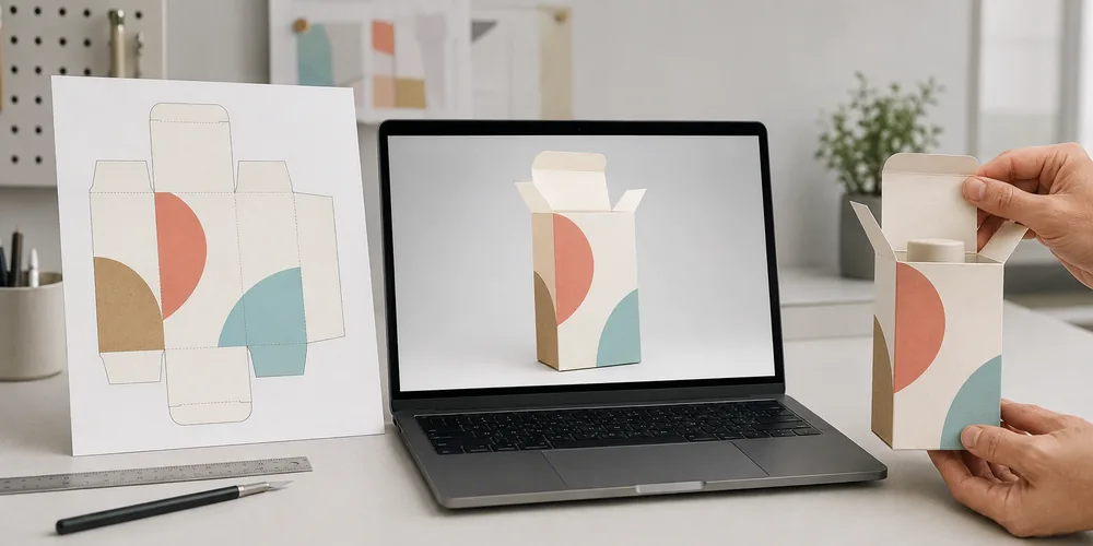
The safest way to review it is to pair three views:
- The editable flat dieline with labeled technical layers.
- A digital 3D view showing how artwork wraps around the package.
- A cut and folded physical sample made from the planned material or a close substitute.
At Packaging NextGen, these views are treated as separate checks. The flat file tests artwork and technical setup, the 3D model tests visual continuity, and the sample tests real fit, folds, closures and assembly.
Dieline Anatomy: Every Line and Area Explained
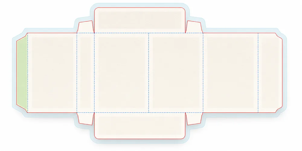
Not every supplier uses the same color or stroke pattern. Always read the file legend first. The terms below describe the usual purpose of each mark, not a universal color code.
| Dieline element | What it controls | What the designer should do |
| Cut or trim line | The edge where material is cut | Extend any edge-to-edge background beyond this line into the bleed |
| Crease, score or fold line | The path where the material bends | Keep small text and critical details away from the fold |
| Perforation line | A line of small cuts made for opening or separation | Avoid placing barcodes or essential copy across it |
| Bleed area | Extra artwork outside the final cut edge | Extend colors, patterns and photos to the full bleed boundary |
| Safe zone | The protected area inside cuts and folds | Keep logos, text, barcodes and required information inside it |
| Glue flap or glue area | The surface used to join panels | Keep ink, coating and important artwork out unless the supplier approves them |
| Registration marks | Production marks used to align printing and finishing | Leave them under prepress control and outside the consumer-facing design |
| Technical notes | Material, dimensions, grain, die number or machine guidance | Preserve them on a separate non-printing layer |
| Window or knockout | An opening or area without normal print coverage | Confirm its edge, film, adhesive and artwork clearance |
| Finishing mask | The area for foil, white ink, varnish, embossing or spot coating | Use a separate named layer or spot-color plate as requested |
Cut Line Vs Crease Line
The cut line forms an outer edge or opening. The crease line weakens or compresses the material so it bends in a controlled place. Confusing the two can create a missing panel, a detached flap or a box that cannot close.
Bleed Vs Safe Zone
Bleed and safety work in opposite directions. Bleed pushes background artwork beyond the cut to prevent an unwanted white edge after small production shifts. The safe zone pulls important content inward so the same shifts do not trim text, logos or codes.
If the supplier requests 3 mm bleed, extend any image or background touching a cut edge by 3 mm past that edge. Do not assume that 3 mm fits every job. Large corrugated displays, labels, flexible packs and specialist converting lines may require another value.
Glue Areas And No-Print Zones
Adhesive bonds best to a surface prepared for it. Heavy ink, lamination, varnish or foil can weaken the bond. A glue zone may therefore be left free of print and coating. If a visual background appears to continue over the flap, ask the converter whether a knockout is needed under the adhesive.
Are Dieline Colors Universal?
No. One supplier may use solid red for cutting and dashed blue for creasing, while another may use named spot colors or CAD line types. Some files use black, red and green. Others rely more on layer names than visible color.
Never approve a packaging dieline based on color alone. Check the legend, layer names and supplier instructions. Technical strokes may need to be set as separate spot colors with overprint, then excluded from the final print plates. Flattening every layer into CMYK artwork can accidentally print a cut or fold mark on the package.
A clean working file might separate these items:
- Artwork
- Cut
- Crease or score
- Perforation
- Bleed guide
- Safe-area guide
- Glue or no-print zone
- White ink
- Foil
- Spot varnish
- Emboss or deboss
- Notes and dimensions
Dieline Dimensions: Internal Size, External Size and Material Thickness
A packaging size is incomplete unless everyone knows whether it refers to the inside or outside of the assembled pack. The difference matters because paperboard caliper, corrugated flute and multi-layer structures occupy space.
Internal dimensions describe usable space for the product. External dimensions describe the finished outer size, which affects shipping cartons, retail shelves and freight calculations. A structural designer may also work with score-to-score measurements on the flat blank.
Before a dieline is drawn, confirm:
- The order of length, width and depth used by the supplier
- Whether measurements are internal or external
- The maximum product size, not only the listed nominal size
- Space needed for an insert, booklet, cable, cap or protective pad
- Material thickness and compression
- Closure and assembly clearance
- Filling or packing method
- Product movement during transit
A carton that fits a rigid sample with zero clearance may become too tight after ink, coating, folding and production tolerances are added. For irregular products, measure the widest, deepest and tallest points and test a physical blank.
How to Read a Dieline Without Placing Artwork on the Wrong Panel
Start by identifying the glue seam. On many folding cartons, this helps reveal the sequence of the main panels. Then label the front, right side, back and left side based on how the carton wraps when assembled. Mark the top and bottom closures separately.
Use this review order:
- Find the main display panel. This is usually the front seen on shelf or in the product image.
- Trace the connected side panels. Follow each crease as though you were wrapping the blank around the product.
- Locate the glue flap. It normally joins the last body panel to the first.
- Check top and bottom orientation. Fold the drawing mentally or use a 3D preview to see which text must rotate.
- Mark hidden areas. Dust flaps, locking tabs and inner walls may be partly or fully concealed.
- Inspect adjoining artwork. Patterns crossing a fold need alignment allowance; a fold is not a perfect visual seam.
- Check the opening experience. Make sure instructions and messages appear in the intended order as the user opens the pack.
Print the dieline at actual size, cut it out and fold it when the structure is simple. This low-cost check catches many orientation mistakes that are easy to miss on a monitor.
Who Creates a Packaging Dieline?
The approved production dieline should usually come from the packaging converter, printer, structural designer or die maker responsible for the job. They understand the material, machinery, tolerances, grain or flute direction, closure style and assembly method.
A graphic designer may build a simple concept template or clean a supplied dieline for artwork placement. Online generators can also create a useful starting file. Neither route removes the need for supplier approval.
Roles often overlap, but responsibility can be divided like this:
| Role | Main responsibility |
| Brand or product team | Product measurements, content, legal copy, user needs and approval |
| Structural packaging designer | Panels, clearances, flaps, folds, closures and material behavior |
| Graphic designer | Artwork hierarchy, typography, images and correct panel placement |
| Converter or printer | Machine limits, print setup, die cutting, creasing, glue and final file rules |
| Prepress operator | Color separation, trapping, overprint, image and font checks, plate-ready output |
| Die maker | Cutting and creasing tool setup where a physical die is used |
How to Create a Packaging Dieline Step by Step
1. Define The Product And Packaging Job
Record product dimensions, weight, fragility, retail or shipping conditions, opening needs, required information and order quantity. A folding carton for a light cosmetic bottle needs different engineering from a corrugated box carrying several glass containers.
2. Choose The Packaging Structure
Select a carton, mailer, sleeve, pouch, tray, label or insert format based on the product and packing process. Do not choose a structure only from its 3D appearance. Review its material use, closure, assembly time, protection and filling method.
3. Confirm The Material
Paperboard caliper, corrugated flute, plastic film, label stock and molded insert thickness all affect dimensions and bend behavior. The dieline must reflect the material planned for production.
4. Build Or Obtain The Structural Drawing
Use an approved CAD standard, a supplier template or an accurately drawn vector layout. Keep panels and flaps dimensionally linked where the software allows it. For a production order, ask the converter to verify or supply the final drawing.
5. Add And Label Technical Paths
Place cut, crease, perforation, glue and finishing information on clearly named layers. Use the printer’s spot-color names, line weights and overprint settings. Do not guess a color legend from another supplier’s file.
6. Add Bleed And Safe Areas
Apply the exact bleed and safety distances specified for the job. Extend backgrounds into bleed and keep critical content inward from cuts, creases and seams.
7. Place The Packaging Artwork
Add graphics beneath the technical layers so the dieline remains visible during review. Rotate top, bottom and side artwork according to the assembled pack. Check that small legal copy stays readable at final size.
8. Review The Package In 3d
A 3D preview helps identify upside-down panels, broken patterns, hidden logos and awkward opening sequences. The Pacdora review explains where browser-based dieline and mockup tools save time and where production review is still required.
9. Make A Physical Prototype
Cut and assemble a plain sample, then test the real product inside it. A prototype reveals board stiffness, fold resistance, locking-tab pressure, glue access, product movement and hand-assembly issues. For more on sample development, see this guide to 3D printing innovations in packaging.
10. Preflight And Request Written Approval
Run artwork checks, send the editable file and PDF proof, and obtain confirmation from the production supplier. If the supplier changes the dieline, move the approved artwork to the latest file and repeat the review.
Illustrator vs ArtiosCAD vs Pacdora for Dielines
No single tool is best for every stage. Packaging NextGen recommends matching the tool to the decision being made.
| Tool | Best use | Important limit |
| Adobe Illustrator | Vector artwork, layer control, type, spot colors and inspection of supplied dielines | It is not a packaging-engineering CAD system and does not automatically account for every material or machine rule |
| ArtiosCAD | Parametric structural design, folding cartons, corrugated packs, displays, fitments and manufacturing data | It requires specialist knowledge and is more than many small design teams need for artwork placement |
| Pacdora | Fast template selection, custom-size concepts, artwork wrapping and 3D presentation | A generated template or render still needs converter approval before production |
Illustrator can be appropriate for placing artwork on an approved dieline and for drawing simple concept structures. ArtiosCAD is stronger when the project needs structural engineering, resizable standards, material-based calculations or manufacturing data. Pacdora is useful for quick visualization and client review.
The risky claim is that a dieline must always be created in one named application. The real requirement is an accurate, editable, supplier-approved structural file that fits the chosen material and equipment.
Which Dieline File Format Should You Use?
The correct format depends on the next person and system in the workflow.
- AI: Useful for editable vector artwork and technical layers in Illustrator.
- PDF: Useful for proofing and exchanging vector content when exported correctly. Ask whether editability and layers must be preserved.
- EPS: An older vector exchange format still used in some print workflows, but it may not preserve newer transparency or layer behavior well.
- DXF: Common for exchanging CAD geometry and cutting information.
- CF2: Used in some packaging CAD and die-manufacturing workflows.
- JPG or PNG: Suitable only as a visual preview, not as the master production dieline.
Send the editable source file plus a reference PDF unless the printer requests another set. Package linked images and fonts where required. For readers learning adjacent production language, this guide explains what collate means when printing and why job instructions need to be precise.
Packaging Artwork Preflight Checklist
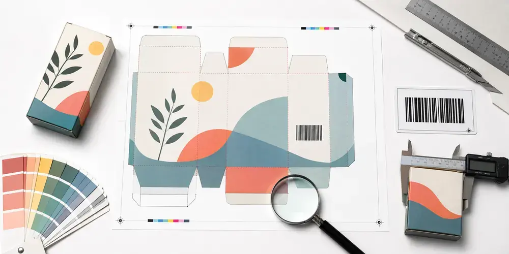
Use this checklist after every structural or artwork revision. Packaging NextGen advises assigning a version number and approval date so the team can identify the exact file sent to production.
Structure And Size
- Confirm the current, supplier-approved dieline version.
- Verify internal and external dimensions.
- Check product clearance, insert space and material thickness.
- Confirm panel names, top and bottom, front and back.
- Check glue flaps, locking tabs, windows and perforations.
Artwork And Type
- Extend backgrounds to the requested bleed boundary.
- Keep logos, type and required copy inside safe areas.
- Check text orientation on every panel and flap.
- Inspect spelling, ingredients, warnings and contact details.
- Outline or package fonts according to the supplier’s rule.
- Confirm linked images are present and have enough resolution at final size.
Color And Technical Layers
- Use the requested color mode and profiles.
- Confirm Pantone or other spot-color names where used.
- Separate cut, crease, white ink, foil, varnish and emboss layers.
- Check overprint settings on technical and special-ink objects.
- Remove accidental RGB objects or unused swatches if requested.
- Make sure dieline strokes are not part of the consumer-facing print artwork.
Barcodes And Codes
- Keep the entire barcode and its quiet zones away from folds, cuts, seams, flaps, perforations, tight curves and rough surfaces.
- Verify size, contrast and orientation for the printing method.
- Print and scan a proof at final scale.
- Recheck the encoded data after any artwork replacement.
Proof And Production
- Compare the flat file with the 3D view.
- Assemble a physical blank at actual size.
- Test the real product, insert and closure.
- Review a printed proof for color and small text.
- Record written approval from the brand and supplier.
Dielines for Different Packaging Types
Folding Cartons
Folding-carton dielines use panels, dust flaps, tuck flaps and a glue seam. Paper grain, board caliper and crease setup affect how cleanly the carton folds and whether printed areas crack.
Corrugated Boxes
Corrugated dielines must account for flute type, score allowance, joint style and material thickness. Large panels may flex, and inside dimensions can change when scores fold. CAD standards such as common corrugated case codes provide useful starting structures.
Flexible Pouches And Bags
A flexible-pack layout may contain front and back panels, gussets, seals, zipper areas, hang holes and tear notches. Distortion, seal clearance and repeat direction matter as much as the visible panel edges.
Labels And Sleeves
Labels need trim, bleed and safe boundaries along with unwind direction, gap, corner radius and application orientation. Shrink sleeves may require distortion compensation because artwork changes shape when the film shrinks around the container.
Rigid Boxes And Inserts
Rigid-box artwork may use separate wraps, greyboard pieces, turn-ins and lining papers rather than one simple carton blank. Inserts require product tolerances, finger access and retention tests.
Retail Displays
Display dielines can include multiple pieces, shelves, locking tabs and load-bearing areas. Weight, assembly sequence and shipping configuration should be tested with a full physical sample.
12 Common Dieline Mistakes That Cause Production Problems
- Using an old dieline after the supplier has revised dimensions.
- Treating line colors as universal without reading the legend.
- Placing a logo or small text too close to a trim or crease.
- Ending a background at the cut line instead of extending it into bleed.
- Printing artwork, coating or foil inside an unapproved glue area.
- Rotating top or bottom copy the wrong way.
- Scaling a dieline without accounting for material and closure changes.
- Flattening technical paths into the CMYK artwork.
- Putting a barcode on a seam, fold, curve or perforation.
- Approving only a 3D render without making a physical blank.
- Sending a raster preview instead of editable vector production files.
- Starting mass production without converter approval and version control.
From Dieline to Finished Package
After approval, the printer prepares color separations, imposition and plates or digital press data. The flat sheets are printed and may receive coating, foil, embossing, lamination or other finishes. Cutting and creasing can then be completed with a flatbed die, rotary die, laser system or digital cutting table, depending on the material, volume and equipment.
The blank is stripped from waste, folded and glued or shipped flat for later assembly. Quality checks compare cut position, crease quality, color, glue strength, barcode scan results and final dimensions against the approved sample and specification.
The dieline itself should not appear as visible technical strokes on the finished package. Its job is to guide production while remaining separate from the printed consumer design.
Final Dieline Advice Before You Print
A strong packaging dieline does more than outline a box. It connects product measurements, material behavior, artwork, print setup, cutting, folding, gluing and user experience in one controlled file. Read the legend, confirm dimensions, protect bleed and safe areas, keep technical layers separate, scan codes at final size and test a physical sample.
Packaging NextGen treats supplier approval as the final gate. Software can speed up drawing and visualization, but the production partner must confirm that the approved version fits the material, equipment and job specification before the full run begins.
Frequently Asked Questions
Is “Dieline” One Word Or Two?
Both “dieline” and “die line” appear in print and packaging language. “Dieline” is common when referring to the full flat packaging template, while “die line” may also describe a cutting path. Use the term preferred by your printer, but keep file naming consistent.
Is A Dieline The Same As A Packaging Template?
They can refer to the same flat layout, but “template” is a broader term. A visual template may lack production data. A production dieline should include accurate structure, technical paths, dimensions or notes, and supplier-approved setup.
Is A Dieline Printed On The Final Packaging?
No. Technical cut and fold strokes guide prepress and converting; they should not print as visible marks on the finished package. Keep them on separate named layers or plates according to supplier instructions.
How Much Bleed Should A Packaging Dieline Have?
Many suppliers request 3 mm or 0.125 inch, but this is not universal. The correct bleed depends on package size, print method, material and equipment. Follow the value in the job specification.
What Is The Safe Zone On A Dieline?
The safe zone is the area where important artwork has lower risk of being trimmed or disrupted by a crease. Logos, text, barcodes and required copy should stay within the safe boundary supplied for the job.
Can I Create A Dieline In Adobe Illustrator?
Yes, Illustrator can draw vector paths and is widely used to place artwork on dielines. It suits simple concepts and graphic preparation. Complex structures, corrugated allowances and machine-ready engineering are better handled or checked in packaging CAD by a structural specialist.
Can I Resize An Existing Box Dieline?
Do not scale it blindly. Flaps, tabs, scores, glue areas and material allowances may need different changes rather than equal scaling. Ask the supplier for a new size or use a parametric CAD model and test the result.
What Is The Difference Between A Crease And A Score?
The terms are often used together, but the exact process can differ by material and equipment. Both indicate a controlled bending path. The converter’s line legend and production method determine how that path is made.
Do I Need A Physical Prototype If I Have A 3d Mockup?
Yes for high-volume, high-value, unusual or tightly fitted packaging. A 3D model checks appearance and orientation. A physical sample tests material behavior, product fit, folding, closure, glue access and assembly.
Who Should Approve The Final Dieline?
The brand should approve content and appearance, while the printer or converter should approve structural and production suitability. Regulated products may also require legal or compliance review.